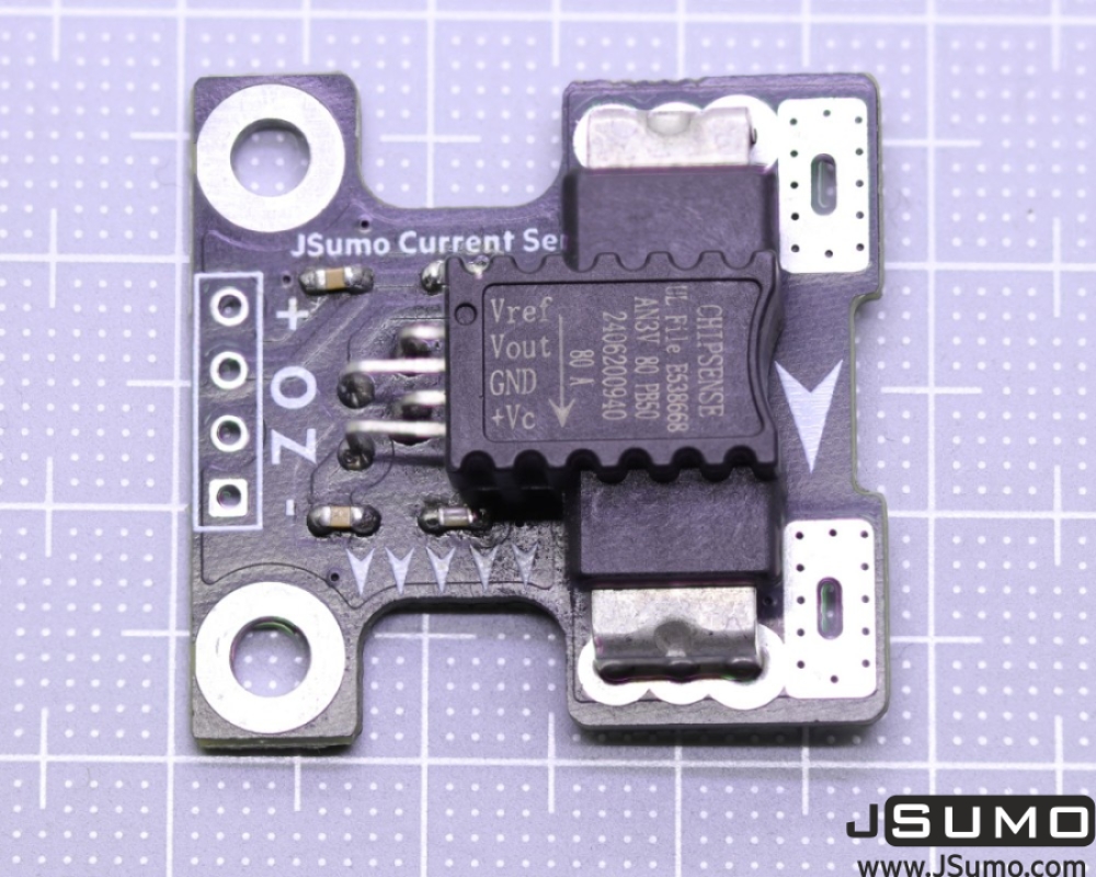
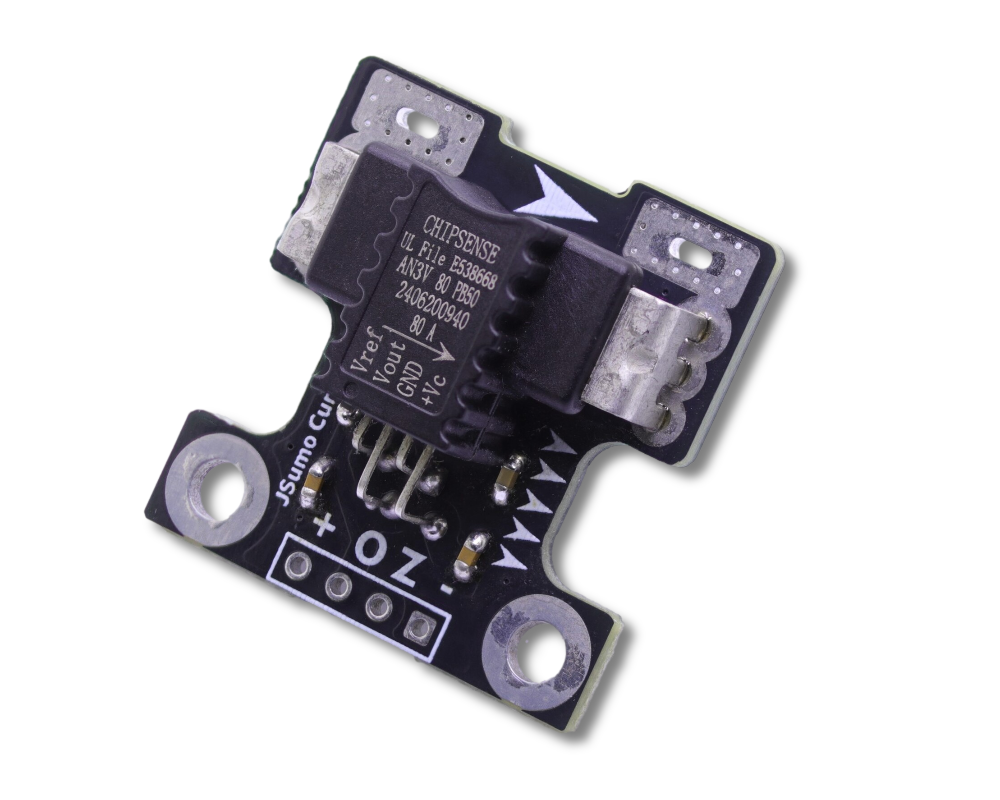
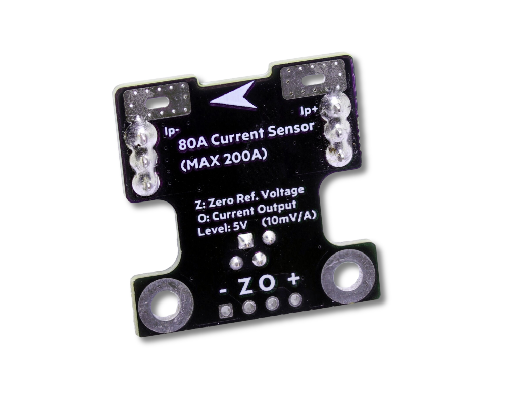
This current sensor module is a compact Hall-effect type sensor capable of measuring bidirectional current up to ±80 Amperes (+80A positive slope, -80A negative slope).
When current flows in the direction indicated by the arrow on the board, the O (output) pin provides an analog voltage equal to the zero reference voltage (2.5V) plus 10 mV per Ampere.
Technical Specifications:
- Operating voltage: 5V
- Measurement range: ±80A
- Output type: Analog voltage (10 mV/A)
- Zero-current output voltage: 2.5V
- Bandwidth: 250kHz
- Board dimensions: 26 mm × 27 mm × 10.5 mm
- Mounting holes: Ø 3.2mm x 2 (Suitable for M3 screw size)
For the datasheet of current sensor IC, please click here.
Current Sensor Applications:
- Motor control applications (which need also regen. current sensing at all situations)
- Robotics projects
- Projects requiring high-current measurement or sampling
Sensor can be used with many projects such as Arduino applications with 5V working voltage.
Pin Definitions
+: 5V Positive voltage.
O: Analog output pin, this pin sends 2.5V at no current.
Z: Analog refence voltage of output that current senor IC. (Approximately 2.5V) Used for reference voltage at calculation. For better accuracy using this recommended.
-: GND pin of the module.
This current sensor module is mostly suited for high-current measurement applications thanks to its thick current path and large solder pads.
Formula to integrate your code
The formula for analog current sensors is very simple. Generally, in bidirectional current measurements, We see the analog voltage as: half of the input voltage (Vcc/2) + multiplied by the current sensor coefficient x current value to obtain the final output voltage.
However, with this AN3V, instead of the reference voltage Vcc/2, there is also a reference pin voltage that provides continuous information of zero current reference (again it will be 2.5V, but this extra pin will give more information for mini fluctations of power supply with same ratio). Taking this into account:
Sensor Output Current Value = (AnalogOutputValue - ReferenceVoltageValue) / CurrentSensorCoefficient
AnalogOutputValue= Voltage Read by your MCU in millivolts from "O-Output" pin.
ReferenceVoltageValue: Voltage read by your MCU in millivolts from "Z-Reference" pin.
CurrentSensorCoefficient: 10mv/A.
So, for example; if you read a voltage of 2.9V and the system voltage is 5V, then 2900-2500/10mV = 40 Amperes.
For test codes and article please check our blog page:
https://blog.jsumo.com/monitoring-high-current-pulses-with-an3v-cc6921b-current-sensor-modules-with-arduino/
 Boards
 Arduino
 Components
 Ebooks
 Magnet
 Mechanics
 Motors
 Drone
Drone Power
Power Robot Bodies (Chassis)
 Robot Kits
 Sensors
 Tools
Tools Wheels